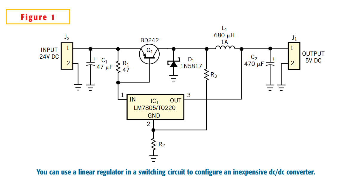
The circuit in is a good choice if you need a power supply with high efficiency and you don't want to use expensive dc/dc-converter ICs. The heart of the circuit is IC1, the common, inexpensive LM7805 linear regulator. The external switch is a pnp transistor; the circuit can easily source more than 1A output current. As an additional feature, the switching circuit automatically turns off if the load draws no or only a few milliamperes of currents. Under these conditions, the circuit works as a normal linear regulator. When you first apply input voltage, current flows through resistor R1 and through the LM7805 to the output. Current also flows through the emitter-base junction of Q1 and turns on the transistor. The current through inductor L1 now rises, and the output capacitor, C2, charges. When the output reaches the rated output of the linear regulator (5V for the LM7805), the regulator switches off its output .
Now, transistor Q1 switches off, because the LM7805 cuts off Q1's base current. When the switch turns off, the voltage across the inductor changes polarity, and current flows through diode D1. The current delivers more charge to C2, until all the energy stored in L1 transfers to C2. If a load is present at the output, the load current discharges C2. When the output voltage drops a few millivolts below the 5V output voltage of the LM7805, the LM7805 again starts sourcing current to the load. This action switches on Q1, and the cycle starts again. Under light- or no-load conditions, all the output current flows through the LM7805, and Q1 always stays off. You can adjust the switcher's start current by selecting the value of R1.
You can also use this circuit for output voltages greater than 5V. You can replace the LM7805 with an LM7812 or an LM7815 to obtain 12 or 15V at the output. For these higher voltages, you should add resistors R2 and R3. These resistors add some hysteresis to the circuit, reducing the switching frequency. Typical values are 2.2 and 2.2 kΩ, respectively. With the circuit in , you can attain efficiency approximately of 75% when you convert 24V to 12V. If you use a 5V regulator, efficiency drops to 65%, but that figure is still better than that of a pure linear regulator.
